
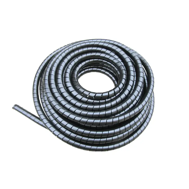
Custom hydraulic hoses are commonly available from 3/16-inch to 2-inch inside diameter, with -4 (1/4 in), -6 (3/8 in), -8 (1/2 in), -12 (3/4 in), and -16 (1 in) covering many mobile and industrial applications. SAE J517, ISO 18752, and manufacturer specifications define dimensional and performance requirements for major hose families. Finished assemblies can range from less than 12 inches to many feet because length is normally cut for the machine rather than selected from a fixed catalog. A 50% increase in hose ID creates 125% more internal cross-sectional area, so diameter has a large effect on fluid velocity and pressure loss. Length also affects friction, routing, bend radius, and fitting position, making both measurements part of the hydraulic system specification.
Hydraulic hose size normally refers to inside diameter, not outside diameter. Dash sizing provides a practical reference: -4 usually corresponds to 1/4-inch ID, -6 to 3/8 inch, -8 to 1/2 inch, -12 to 3/4 inch, -16 to 1 inch, -24 to 1-1/2 inches, and -32 to 2 inches. SAE J517, whose history extends back decades and remains widely referenced in North American hydraulic specifications, covers hose constructions including SAE 100R1, 100R2, 100R12, 100R13, and related types.
| Dash size | Nominal ID | Approx. metric ID | Typical use range |
|---|---|---|---|
| -4 | 1/4 in | 6.4 mm | Pilot and smaller hydraulic lines |
| -6 | 3/8 in | 9.5 mm | Compact equipment and auxiliary circuits |
| -8 | 1/2 in | 12.7 mm | General pressure lines |
| -12 | 3/4 in | 19.1 mm | Medium/high-flow circuits |
| -16 | 1 in | 25.4 mm | Higher-flow equipment |
| -24 | 1-1/2 in | 38.1 mm | Large industrial lines |
| -32 | 2 in | 50.8 mm | High-flow applications |
Diameter matters because fluid velocity rises rapidly when the same flow is pushed through a smaller passage. Moving from 1/2-inch ID to 3/4-inch ID increases diameter by 50%, but internal cross-sectional area rises by about 125%. At an identical flow rate, average velocity in the larger passage is therefore about 56% lower, before differences in actual hose bore and internal construction are considered. That relationship explains why selecting a hose from port thread size alone can produce poor hydraulic performance.
A fitting that screws into the port does not establish the correct hose ID. Pump flow, line function, hose length, fluid viscosity, allowable pressure loss, and manufacturer velocity guidance still need to be checked.
Flow requirements also vary by line function. Pressure lines commonly tolerate higher fluid velocities than pump suction lines, while return lines are often sized to keep backpressure within the equipment manufacturer's limits. A -6 hose might be appropriate for one pressure circuit but too restrictive for another circuit carrying a substantially higher flow rate. In systems built or serviced under 2026-era SAE and ISO practices, the hose manufacturer's published technical data should take precedence over a generic dash-size chart.
Pressure rating adds another variable because two hoses with the same ID can have very different construction. A 1/2-inch one-wire-braid hose and a 1/2-inch two-wire-braid hose are dimensionally similar at the bore, yet their allowable working pressures can differ substantially by product series. Many hydraulic applications therefore use wire braided hydraulic hose when the specified pressure range, flexibility, fittings, and service conditions suit braided reinforcement.
The relationship between pressure and size is not linear. Within many hose families, maximum working pressure decreases as nominal ID increases because a larger bore creates greater force on the reinforced hose wall at the same internal pressure. A manufacturer may consequently rate smaller sizes in a series for noticeably higher pressure than 1-inch or 1-1/4-inch versions. A larger hose should never be assumed to carry a higher pressure simply because it contains more reinforcement material.
Length is more customizable than diameter. Hose ID usually follows standardized sizes, while an assembly may be cut to 17.5 inches, 42 inches, 6 feet, or another specified finished dimension when the hose, fittings, and fabrication equipment permit it. In a sample set of 4 assemblies measuring 18, 36, 72, and 120 inches, every assembly could use the same nominal hose size while requiring different routing allowances and fitting positions.
That flexibility does not make overall length arbitrary. Measuring a straight 36-inch gap between ports and ordering exactly 36 inches can leave insufficient material for bends or equipment movement. Hose routing has to follow the actual installed path while staying within the manufacturer's minimum bend radius. A cylinder connection that moves several inches through its stroke also needs enough hose to accommodate that movement without tension, twisting, or concentrated bending near the fitting.
Measure the installed path, not only the distance between connection points. For a replacement assembly, record the old hose's overall length, fitting reference points, elbow direction, and routing before removal.
Minimum bend radius becomes more restrictive as many hose sizes get larger. A 1/4-inch hose can normally turn within less space than a 1-inch hose from the same construction family. Manufacturer data may show bend-radius differences of 100% or more between small and large sizes in one product line. Routing a larger replacement through the original clamps and openings can therefore create an installation problem even when the new hose improves flow capacity.
Fitting length must also be included in the finished assembly measurement. A hose described as 48 inches overall is not necessarily made from 48 inches of bulk hose because the installed fittings contribute to the assembly dimension. Straight male fittings, female swivel fittings, flanges, 45-degree elbows, and 90-degree elbows use different reference points. With 2 angled fittings on one assembly, angular orientation becomes another required measurement because a correct length with incorrect fitting orientation can force the hose to twist during installation.
Twisting deserves attention because hydraulic hose is designed primarily to flex through its intended bend, not to operate under torsional stress. SAE and hose-manufacturer installation guidance commonly calls for routing that avoids twist and bending immediately behind the fitting. A replacement hose can match the original ID within 0% dimensional difference and still have a shorter service life if the elbow orientation forces torsion into the reinforcement.
Longer assemblies introduce hydraulic considerations as well. Pressure loss through a hose increases with length when bore, flow rate, fluid properties, and internal construction remain unchanged. A 20-foot run therefore cannot automatically be treated like a 5-foot run merely because both use -8 hose. The longer assembly provides 300% more hose length, giving friction more distance over which to affect pressure loss and heat generation.
For long runs, moving to the next suitable hose ID may reduce fluid velocity and pressure drop, although fittings, ports, routing space, and equipment specifications have to support the change. Rigid tubing can also be used for long stationary sections, leaving flexible hose around moving joints. Many industrial systems use this mixed arrangement because steel tube maintains a defined route while hose accommodates movement and vibration at selected connection points.
Temperature further narrows the available size-and-length combination. Hydraulic hose ratings commonly cover broad temperature ranges, but the exact limit depends on tube material, cover compound, hydraulic fluid, and hose series. Operating continuously near the upper temperature rating can affect service life, so a hose rated for a stated maximum should not be selected from diameter alone. A system operating 25% hotter after an equipment modification deserves a fresh check of the hose and fluid specifications.
Fluid compatibility needs the same treatment. Petroleum-based hydraulic oil is common, but water-glycol fluids, synthetic fluids, biodegradable hydraulic fluids, and other media can require different inner-tube compounds. The selected hose should be checked against the manufacturer's compatibility information. Changing from one fluid family to another while retaining a hose installed in 2018, for example, is not enough information to confirm compatibility even if its ID and length remain correct.
Outer diameter matters mainly for installation rather than flow. Two -8 hoses can both have approximately 1/2-inch nominal ID yet use different reinforcement structures and cover thicknesses, producing different outside diameters. That difference affects clamps, protective sleeves, hose guides, bulkhead openings, and bundles. A routing channel with only 10% spare clearance may accept one -8 construction and reject another despite matching nominal IDs.
Available size is also influenced by reinforcement. One-wire and two-wire braided products commonly serve many medium- and higher-pressure applications, while multi-spiral constructions are used where very high pressure and impulse requirements call for them. ISO 18752 classifies hydraulic hose performance using pressure and impulse criteria rather than relying only on traditional construction labels, giving engineers another way to compare hoses introduced under modern international specifications.
Impulse performance matters on equipment where pressure repeatedly rises and falls. A hose may experience thousands or hundreds of thousands of pressure cycles rather than one constant pressure level. For machinery operating 8 hours per day at a repeated cycle, annual cycling can become substantial, so the assembly needs the specified pressure and impulse capability as well as the correct dimensions. Size, pressure class, and reinforcement should be specified together.
Ordering information should therefore go beyond “1/2-inch hose, 4 feet long.” A usable specification can state -8 nominal ID, 48-inch finished assembly length, hose standard or manufacturer series, maximum working pressure, operating temperature, fluid type, and both fitting descriptions. For 2-ended assemblies, record fitting A and fitting B separately, including thread or flange type, sealing method, angle, and orientation where applicable.
-
Hose ID and dash size
-
Finished assembly length and measurement method
-
Maximum working pressure and expected pressure surges
-
Fluid and operating temperature
-
Fitting type, thread, sealing surface, and size at both ends
-
45° or 90° elbow orientation when used
-
Minimum bend radius and available routing space
-
Abrasion, outdoor exposure, and equipment movement
Replacement work adds one more check: the removed hose is useful as a physical reference only when it was correctly specified in the first place. A hose installed 5 years earlier may have been replaced with the wrong length, routed differently after maintenance, or stretched during service. Recording the machine model, hydraulic circuit position, port details, and actual routing provides better information than copying an unidentified assembly without checking its specification.
Custom hose fabrication can accommodate short jumpers and assemblies many feet long, but manufacturer limits, bulk-hose reel length, crimping capability, shipping, and hydraulic performance set practical boundaries. Common IDs from 3/16 inch through 2 inches cover a broad portion of mobile and industrial hydraulic equipment, while specialized hose families extend outside that range. The finished assembly should match the required flow, pressure, temperature, fluid, bend radius, fitting geometry, and routed length rather than treating diameter and length as independent measurements.